

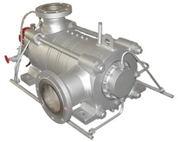
Ks, KsP Series Inducer Horizontal Segmental, Between Bearings
Applications: Designed for handling condensate in the steam and water circuit systems of the thermal power stations that burn organic fuel. May be also used to transfer water in heating plants and water supply systems.
Design: AKs and AKsP series pump units consist of a centrifugal pump, an induction motor, which are connected by means of a rubber-bushed (pin-and-bushing) flexible coupling and mounted on a common fabricated base plate.
The pump as a component of the pump unit is an electrically driven horizontal single-stage (Ks 50-55-2) or multistage ring-section centrifugal pump between bearings, with single flow impeller arrangement.
The suction casing, delivery casing and stage casings (consisting of a shell and an insert in case of the KsP series pumps) are bolted together with tie bolts to form a pump casing. The suction nozzle integrally cast with the suction casing is located horizontally at side (radially to the pump centerline). The discharge nozzle integrally cast with the delivery casing is oriented vertically upwards. The pump casing is supported at the bottom with feet integrally cast with the suction and delivery casings. The pumping unit alignment is maintained during its operation due to dowelling the delivery casing to the baseplate, whilst the other end of the pump can slide axially thus allowing for free expansion of static components.
Pump suction performance is enhanced due to the installation of an inducer upstream of the first stage impeller.
The rotor axial thrust is compensated with a balance drum.
Shaft sealing: by liquid-cooled packed glands (-S) or mechanical seals (-T).
The pump rotor is carried by:
a) in case of KsP series:
- a medium-lubricated internal plain bearing (on the non-drive side) and
- a grease lubricated anti-friction bearing (on the drive side);
b) in case of Кс series: grease lubricated anti-friction bearings.
Sense of rotation of shaft in all the pumps is counterclockwise, if viewed from the drive side.
DN |
mm |
66, 100, 150 |
Q |
m3/h |
88 |
H |
m |
175 |
p |
kg/cm2 |
10 |
t |
oС |
+1 - +160 |
n (sync) |
rpm |
3000 |
Coverage chart of the KsP, Ks Series Pumps:
Performance of the Ks and KsP Series Pumps:
| Pump make | Pump parameters |
||||||
| Capacity, m3/h | Head, m | Speed of rotation, rpm | Power input (r=907 kg/m3), kW | Power input (r=1000 kg/m3), kW | Efficiency, % | NPSH required, m | |
| Ks 50-55-2-S UKhL4 Ks 50-55-2-Т UKhL4 | 50 |
55 |
2920 |
10,5 |
11,5 |
65 |
1,6 |
| KsP 50-55-2-S UKhL4 KsP 50-55-2-Т UKhL4 | |||||||
| Ks 50-110-2-S UKhL4 Ks 50-110-2-Т UKhL4 | 110 |
20,9 |
23,0 |
65 |
|||
| KsP 50-110-2-S UKhL4 KsP 50-110-2-Т UKhL4 | |||||||
| Ks 80-155-2-S UKhL4 Ks 80-155-2-Т UKhL4 | 80 |
155 |
2940 |
43,8 |
48,2 |
70 |
|
| KsP 80-155-2-S UKhL4 KsP 80-155-2-Т UKhL4 | |||||||
| Ks 32-150-2-S UKhL4 Ks 32-150-2-Т UKhL4 | 32 |
150 |
2900 |
18,0 |
19,8 |
66 |
|
Handled Media:
- Condensate up 1 oС to 160 oС